↓ Skip to main content
  1. Blog/

Flipper Zero 5G Expansion Board User Manual (v2.0): Illustrated Setup and Usage Guide

Table of Contents

Audience: Customers new to the 5G Expansion Board.
Key Goal: This guide provides detailed isometric diagrams for all critical setup steps. Each step includes a dedicated visual reference to ensure a smooth, error-free installation.


00. Unboxing and Package Contents
#

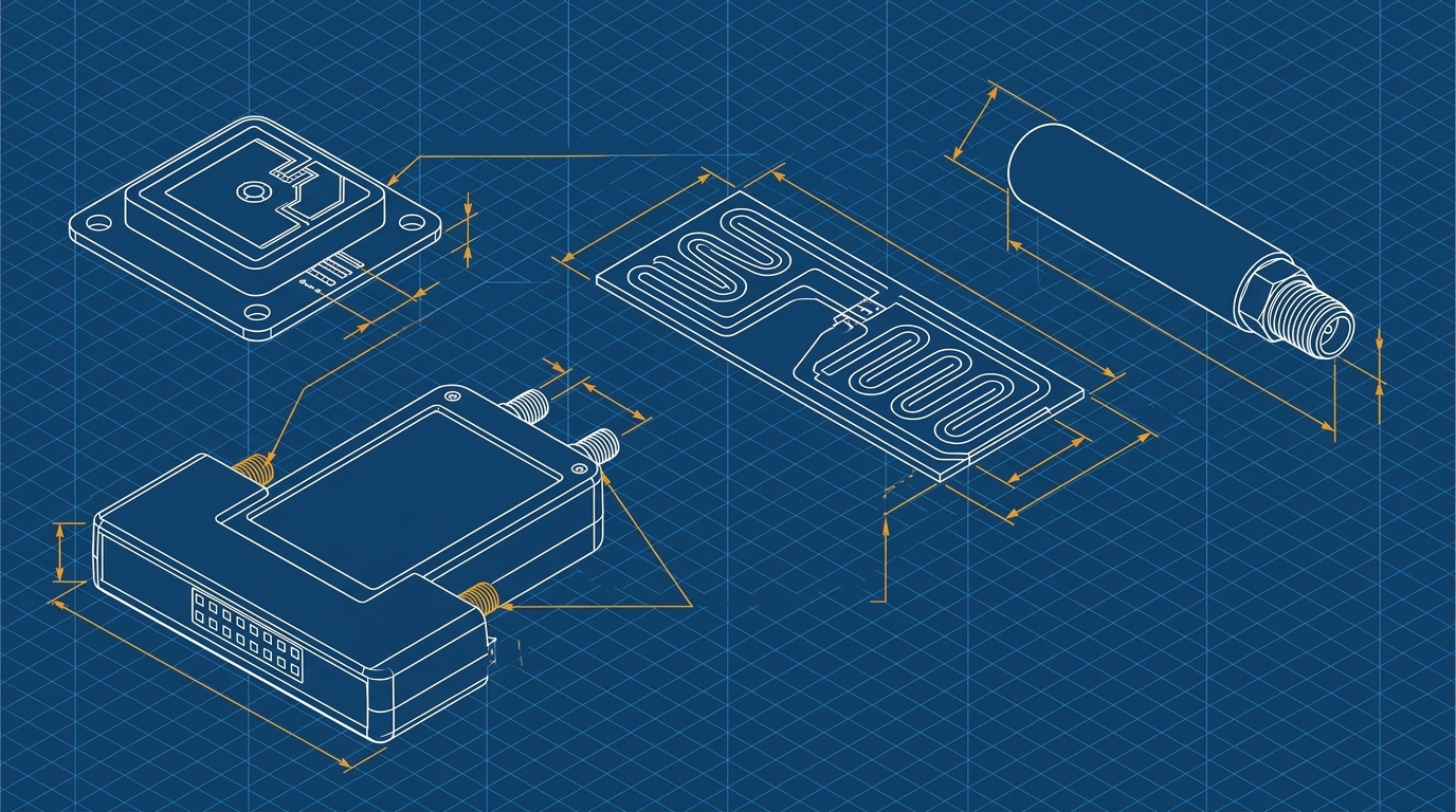
Thank you for choosing the Flipper Zero 5G Expansion Board. Before starting the setup process, please verify that your package contains all the items listed below.

Package Contents
Figure 1: Included package accessories

⚠️ Package Contents Details
#

  • Standard Items Included:
    1. 5G Expansion Board main module x 1
    2. 433MHz whip antenna (short, black whip antenna) x 1
    3. GPS active ceramic patch antenna (square antenna with cable) x 1
    4. Dual-band WiFi adhesive patch antenna (flat, black antenna) x 1
  • Items Not Included (Required Separately):
    • Flipper Zero console (not included with this module)
    • MicroSD card (required for module operation, must be purchased separately)

01. Getting to Know Your 5G Module
#

Before attaching the antennas or connecting the module to your Flipper Zero console, take a moment to familiarize yourself with the key interfaces and hardware layout.

Front Interface
#

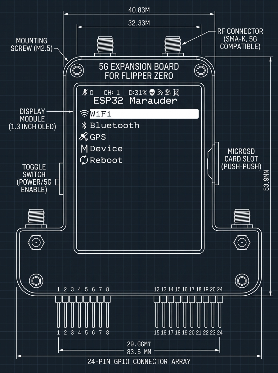
Front Interface Diagram
Figure 2: Front hardware configuration layout

  • LCD Screen: Displays current connection status, IP address, and operation mode.
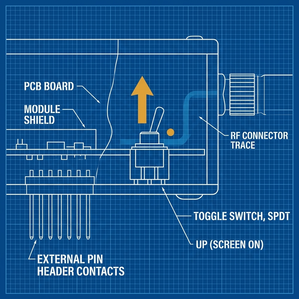
  • Toggle Switch: Controls the power supply to the module screen. Flip the switch upward to turn it on.
  • MicroSD Card Slot: Used for storing firmware configurations and system logs.
  • GPIO Socket: Female header that connects to the male GPIO pins on the top of the Flipper Zero.
  • LED Indicators: Show power and battery charging status.

Side Antenna Ports
#

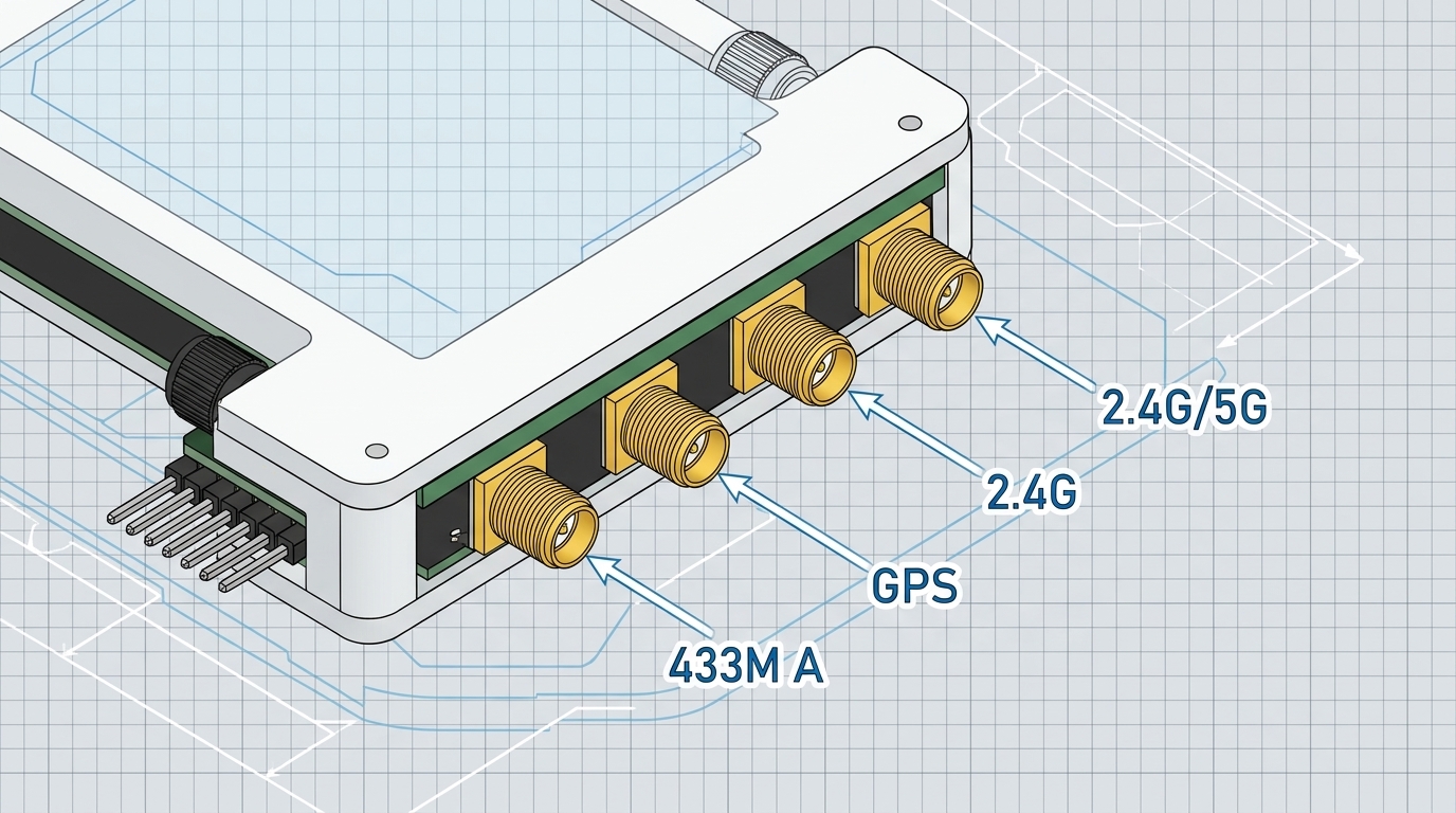
Antenna Ports Diagram
Figure 3: Antenna port locations and labeling

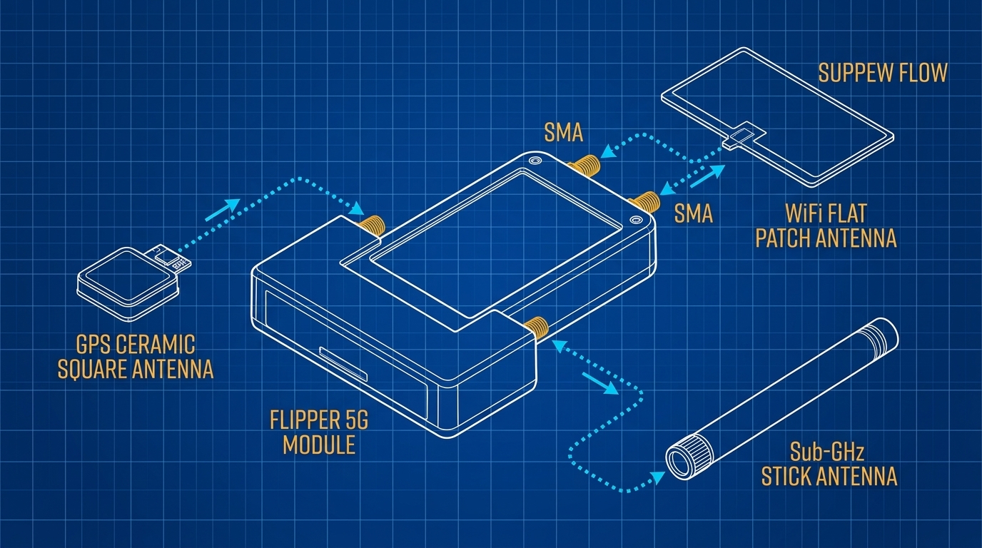
  • 433M A: Connects the 433MHz whip antenna.
  • GPS: Connects the active GPS ceramic antenna.
  • 2.4G and 2.4G/5G: Connects the dual-band WiFi adhesive patch antenna.

⚠️ Production Batch Notice:
The antenna port layout may vary slightly depending on the production batch. For example, the GPS and WiFi ports might be swapped. Always refer to the printed labels on your physical module case instead of relying on memory, preventing signal degradation or hardware damage.


02. Step-by-Step Installation Guide
#

Step 1 | Prepare and Install the MicroSD Card
#

The 5G module requires a MicroSD card to store configuration files.

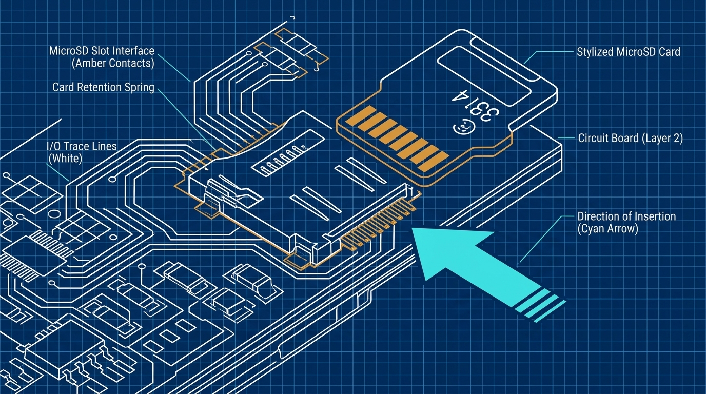
  1. Insertion Direction: Insert the MicroSD card into the slot with the metal contacts facing down. Press the card gently until it clicks into place.

MicroSD Card Slot Close-up
Figure 4: Proper MicroSD card insertion orientation


Step 2 | Install the Three Antennas
#

Secure the three included antennas to their corresponding SMA antenna ports. Hand-tighten each connector until snug, but avoid applying excessive force.

Antenna Installation Diagram
Figure 5: Diagram of antenna connections and routing paths

Antenna TypePort DesignationInstallation Detail
GPS Active Ceramic AntennaGPS PortSquare ceramic housing with an extension cable
Dual-band WiFi Adhesive Patch Antenna2.4G/5G PortFlat, black adhesive patch antenna
433MHz Whip Antenna433M A PortShort, black rigid whip antenna

⚠️ GPS Antenna Orientation Warning
#

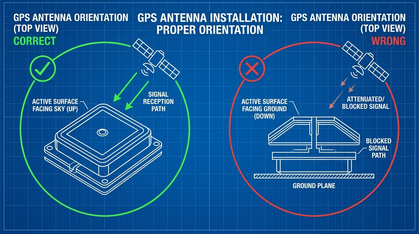
The GPS antenna is highly directional. During installation, the ceramic face (the flat top — the side opposite the double-sided tape) must point upward (facing the sky). Incorrect placement prevents the module from obtaining a satellite lock.

GPS Antenna Orientation Comparison
Figure 6: Proper (facing up) vs. improper (facing down) GPS antenna placement


Step 3 | Mount the Module onto Flipper Zero
#

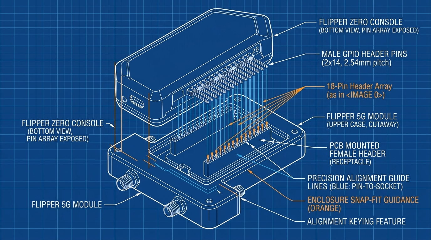
Insert the 5G module into the GPIO pins on top of the Flipper Zero.

  1. Power off the Flipper Zero to prevent potential hardware damage from hot-plugging.
  2. Align the GPIO pins on top of the Flipper Zero with the socket on the bottom of the module.

GPIO Alignment Diagram
Figure 7: GPIO alignment guidelines and layout

  1. Apply even pressure with both hands to push the module firmly down.
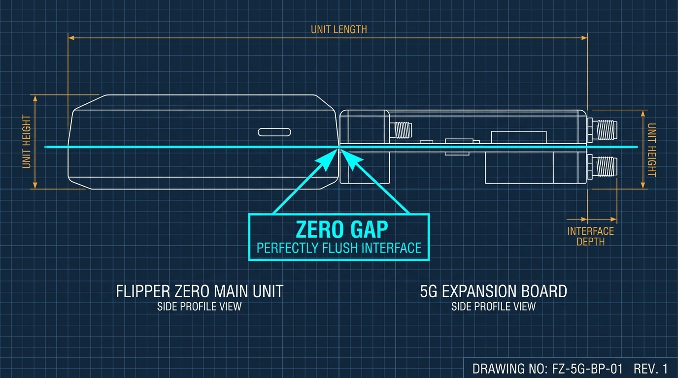
  2. Verify the fit: Inspect the module from the side. The module must sit completely flat against the Flipper Zero with no visible gap.

GPIO Fit Verification
Figure 8: Correctly aligned and fully inserted GPIO connection


Step 4 | Flipper Zero Software Configuration
#

Once mounted, power on your Flipper Zero and configure the GPIO pins.

If you use the Momentum firmware, follow these steps:

  1. Power on the Module Screen: Flip the toggle switch on the left front side of the module to the UP position.

    Toggle Switch UP position
    Figure 9: Setting the toggle switch to the UP position to enable the screen

  2. Configure GPS Pins:

    • Navigate to: Protocol Settings > GPIO Pin Settings > GPS Pin
    • Set the value to 13 or 14 (depending on your specific hardware version specifications).
  3. Configure ESP32 Pins (WiFi/Bluetooth functions):

    • Navigate to: Protocol Settings > GPIO Pin Settings > ESP32 Pin
    • Set the value to 15, 16.
  4. Configure the 433MHz Sub-GHz Module:

    • Navigate to: Sub-GHz > Advanced Settings > set the Module to External to enable the external antenna.

Step 5 | Charging and Battery Level Check
#

The module features a built-in rechargeable battery.

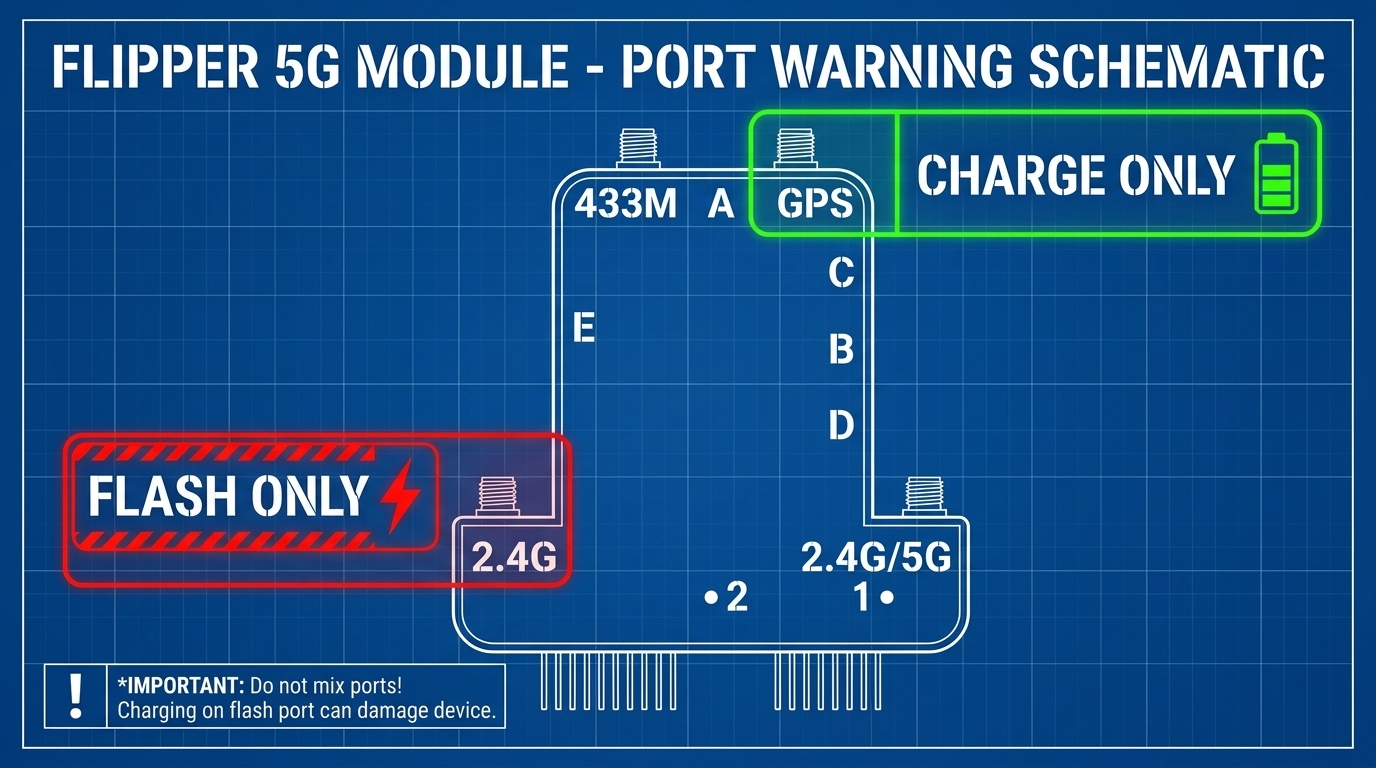
USB-C Port Locations
Figure 10: Top port (CHARGE ONLY) vs. side port (FLASH ONLY)

  • Top USB-C Port: Designed for charging only (labeled CHARGE ONLY). Use this port for regular charging.
  • Side USB-C Port: Designed for firmware flashing only (labeled FLASH ONLY). Don’t connect a charger to this port as it doesn’t charge the battery.

Battery Indicator LEDs:
#

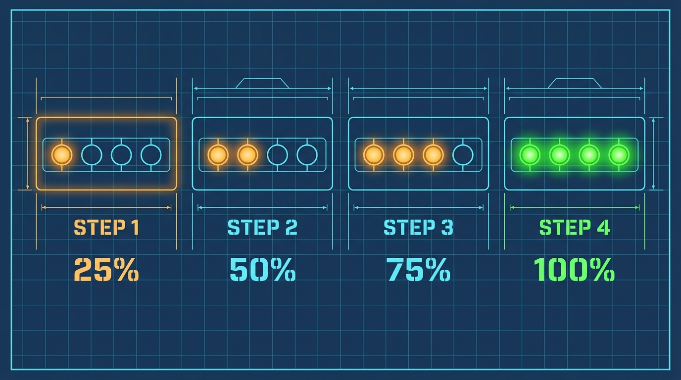
The front of the module features four battery status LEDs, indicating different remaining charge levels.

Battery Level Indicator LEDs
Figure 11: Battery level readings for the four status LEDs


03. Troubleshooting Checklist (For Beginners)
#

If your module doesn’t work as expected, verify the following setup details:

  • Is the GPIO connection fully seated? The module must sit flush with the top of the Flipper Zero, leaving no gaps (see Figure 8).
  • Is the GPS antenna oriented correctly? The ceramic side must face the sky (see Figure 6).
  • Are the antennas connected to the correct ports? Layouts vary between batches. Verify the printed text labels on the casing (see Figure 3).
  • Is the screen switch set to UP? (see Figure 9).

04. Firmware Updates and Flashing (Advanced Users)
#

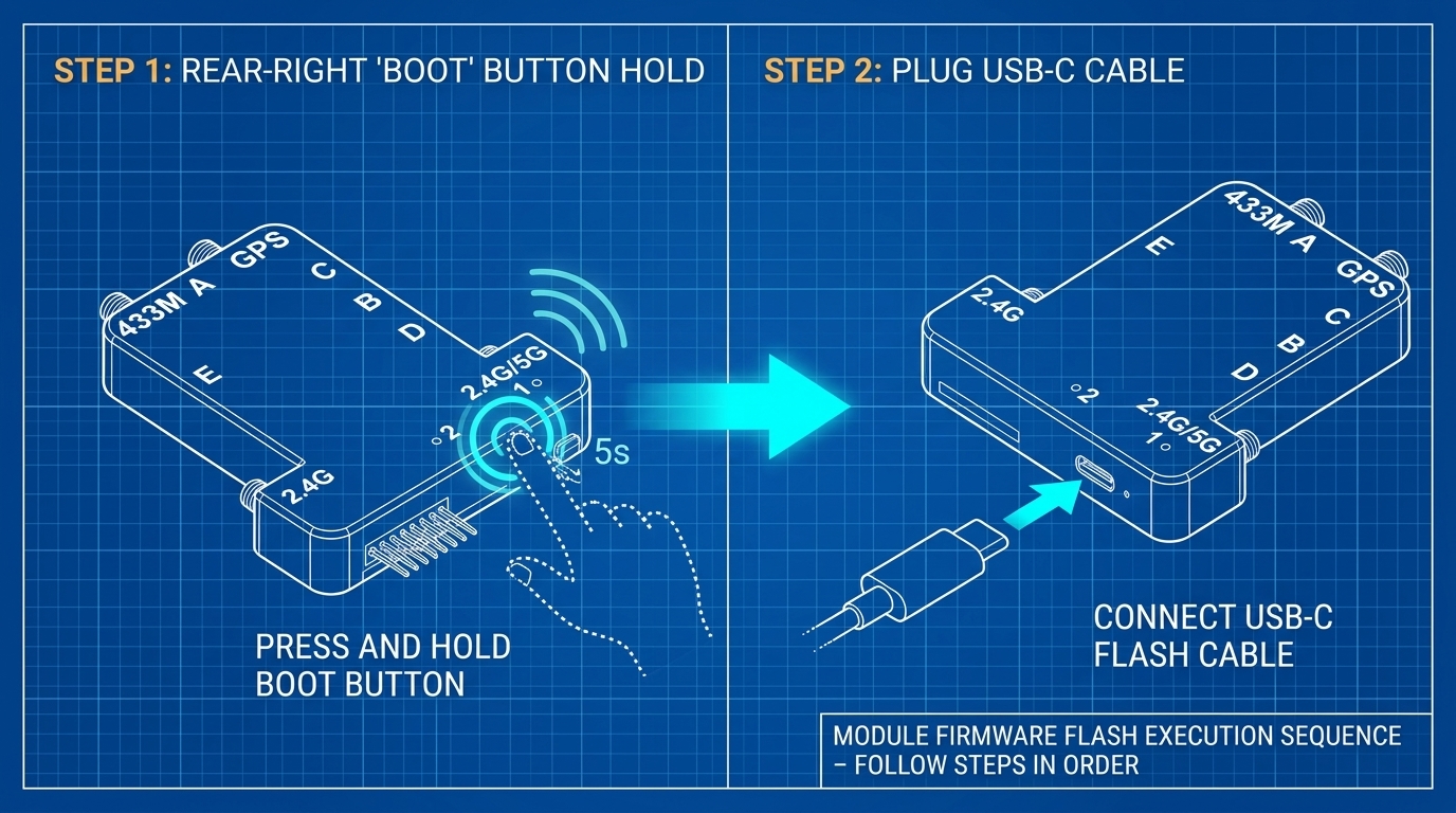
When new firmware releases are available, flash the module using the side USB-C port.

  1. Connect a USB-C cable to your computer.
  2. Important Flashing Sequence: Hold down the boot/flash button on the back/right side of the module, then insert the USB-C cable into the side USB-C port (FLASH ONLY) to enter bootloader mode.

Firmware Flashing Sequence
Figure 12: Proper sequence for holding the boot button and connecting the flashing cable